CNC Example 01: Generating OutQueue Directly
See the CNC01_direct.project sample project in the installation directory of CODESYS under ..\CODESYS SoftMotion\Examples.
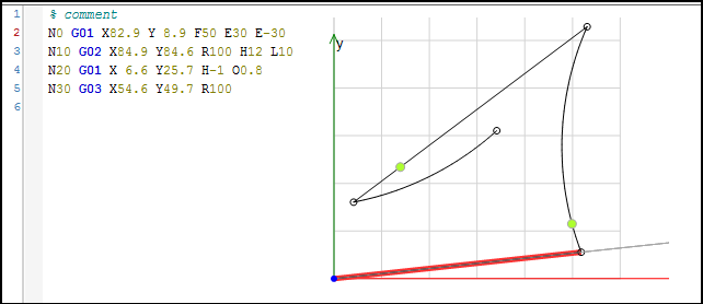
This example shows a CNC program with two axes. Four positions are approached in the X/Y-plane with a defined velocity and acceleration. The program sets two path switch points on the path. The program is written directly into a data structure by using the SMC_OutQueue compile mode.
Creating an NC program in the CNC editor
Create a
CNCdirectproject with a SoftMotion controller.Insert a CNC program object named
Example.Select the Implementation
Din66025and the Compile modeSMC_OutQueue.Specify the following motion blocks:
CNC editor:
Creating a drive interface and PLC configuration
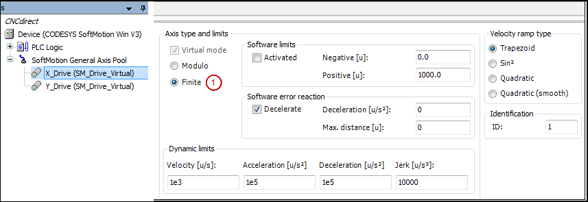
Define a drive structure with two linear drives as follows:
Insert two virtual drives
X_DriveandY_Drivebelow the SoftMotion general axis pool.Set the Axis type parameter to
Finite(1).Configuration editor:
Creating an IEC program
Add a new CFC program Ipo to the application and configure a cyclic task with an interval of 3 ms.
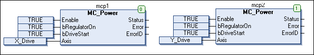
Activate the drive with the
MC_Powerfunction block.POUs:
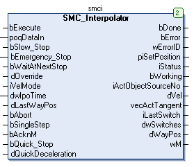
Insert the
SMC_InterpolatorPOU. The function block converts a path defined by GEOINFO objects into discrete path points. The function block receives the address of the created CNC program at the inputpoqDataIn. Then the IEC task cycle time has to be written to the inputdwIpoTime. You can specify these as constant values at the inputdwIpoTimeor you can use the variabledwCycleof the axis group structure from the PLC configuration. The advantage of this is that the correct time is automatically used as the interpolator input when you change the task cycle time.POU:
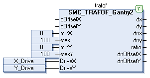
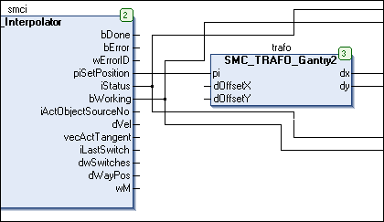
In this example, a gantry system will be controlled. For this purpose, insert an instance of the inverse and forward transformation function blocks from the
SM_Trafolibrary. The forward transformation function block contains the drives as inputs. The inverse transformation function block has to contain the set position of the interpolator. The forward transformation in the example is required for the visualization only.Function block instance:
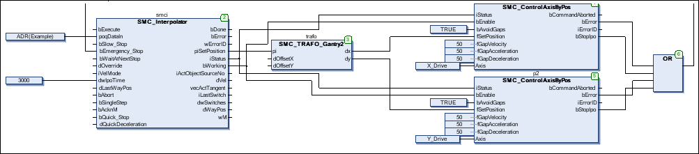
The outputs of the function block (the axis coordinates) have to be written to the drives. This is done with the
SMC_ControlAxisByPosfunction block. Because the application does not guarantee that the outputs of the interpolator are constant (e.g. the path ends at a point other than where it began), activate the gap avoidance (bAvoidGaps,fGapVelocity,fGapAcceleration, andfGapDeceleration). Then connect theStopIpooutput to thebEmergency_Stopinput of the interpolator and connect interpolator outputiStatusto the respective inputs of the axis control function blocks.Above all, pay attention to the correct order of function blocks when programming with CFC.
CFC:
Creating an operating interface and a testing interface
Link two visualization objects to a new visualization: the template of the interpolator and the template of the transformation. You need to use placeholders to link these to the respective function block instances (here: Ipo.smci and Ipo.trafof).
Commissioning
Compile and start the created program. The program executes the CNC motion as soon as the Execute input of the interpolator has been set. After the program has run completely, you can apply a new rising edge to restart it.
Note the function of the path switches that are also displayed in the visualization of the interpolation function block.